Showing posts with label LDD. Show all posts

Thursday, 16 April 2015

Leaps and Bounds

Having posted an update on my MOC City layout last time out (you can read it here if you missed it) I'm willing to bet that there are a few sceptics out there who predicted another 2 year wait for the next installment.... I can't really blame you, to be honest - my track record on this project has been pretty abysmal - but on this occasion I'm delighted to prove you wrong. Truth be told, I actually couldn't wait to start working on it again, and despite a busy last few weeks since I last wrote I still managed to carve out a few evenings to dive back in and make some progress. OK, so perhaps not exactly leaps and bounds, but tangible progress nonetheless.


The obvious place for me to focus my renewed construction efforts was the front left corner of the layout which was looking decidedly bare, consisting as it did of just a bunch of dark bley baseplates held together by a few lengths of 9V track and a sprinkling of 1 x 2 and 2 x 2 dark bley tiles. As you can see in the pictures above and below (click to enlarge) I started out by finally completing the job of boxing in the track loop with light bley bricks to a height of 3 bricks. While this might not seem like a significant milestone, given my pitifully slow rate of progress to date - almost four and a half years to get to this point - it's still probably worth celebrating....


That minor milestone having been achieved, I continued to lay down successive layers of light bley brick, increasing the height of the inner and outer walls on the left side and front left corner of the layout to 7 bricks. It was a repetitive task but therapeutic nonetheless; people talk about being 'in the zone', and so far as building with LEGO is concerned I reckon that simple building tasks like this are about as 'in the zone' as it gets - you rapidly slip into autopilot and it feels almost hypnotic at times. Certainly the time seemed to pass very quickly.


The volume of brick needed to build on such a scale is considerable and easily underestimated, but having initially sketched out the design on LDD I already knew what would be required and had long since sourced the necessary elements - you can see some of them bagged up and ready to be pressed into use in the pictures above and below (click to enlarge).


Encouraged by my progress I pressed on and eventually got as far as raising the whole left side of the subterranean level of the layout up to full height (below - click to enlarge) before calling it a day. All that's left to do now is finish up the right side and then cover the lower track loop with a roof and the visible sections of the subterranean level will be complete. That'll be another milestone worth celebrating as at that point I'll finally be able to start work on the upper level where most of the action will be.


I've also now finished up the left side of the underground platform, thus completing the platform section adjacent to the tracks. I'm clearly not going to be able to fit many minifigures on it, but that having been said, there's probably about as much space on there as on some London Underground platforms so maybe it's more realistic than I'd anticipated....


One thing I've tried to remain mindful of is the question of portability. Sure, a 288 x 160 stud LEGO layout built on two levels is never really going to be truly portable, but I'm nevertheless taking the view that there's no point in just building something which will forever reside in my study unseen by anybody but me and readers of Gimme LEGO.... It's always been my intention to build with a view to eventually displaying the finished layout at events, and so to this end I'm trying to address potential portability issues as they arise rather than trying to figure it all out at the end.


A good example of this is provided by the underground station platform above. I figured that this would need to detach from neighbouring sections in order that it could be safely transported. It soon became evident however that the way I'd designed it in LDD would necessitate me literally breaking it apart for transportation and then having to rebuild it at my destination. I therefore needed to devise a different way of joining the sections together which would enable the platform to detach in a non-destructive fashion and I arrived at the solution below (click to enlarge).


As you can see from the picture above, the main platform section is attached by way of Technic pins and detaches with a minimum of fuss. The arch overhanging the front of the platform is part of the inner wall enclosing the track and will eventually help to support the roof and the structures above. When the platform section is attached, the lower aspect of this arch rests on a 1 x 1 tile which is part of the outer wall of the detachable platform section; this will help to support the weight pressing down on the arch while still allowing the detachable platform section to be easily removed.


So now there's finally somewhere for the minifig residents of my City layout to catch the train; my minifig alter ego seems to have missed this one, but there'll be another along in a minute....

                                                                                        LEGO City Layout : next blog entry -- >

Friday, 20 March 2015

Back on Track!

Long-time readers of this blog might recall that ages back I posted a number of entries about the design and construction of my own LEGO City Layout. The first time I posted about it (here) was way back in November 2010 when, while suffering from LEGO withdrawal after a few days away from home, I'd fired up my laptop, loaded up LDD and started to play around with a possible design. As described in that initial post, what I had in mind was a city layout on two levels, with a subway train running below ground and a cityscape on the upper level featuring an outer oval of railway track enclosing a central area. The central area would be filled with roads lined with modular buildings and hopefully some structures that I'd designed myself, plus some railway sidings and a small railway tunnel running through a LEGO rock formation. The upper level would be landscaped so that it didn't just look like a bunch of baseplates chucked together with a few buildings on top, and the icing on the cake would be to make the whole layout modular so that it was feasible to deconstruct, transport and reassemble it for the purpose of displaying it at events.


Over the subsequent weeks and months the basics of the design gradually came together in LDD as you can see from the June 2011 LDD screengrab above (click to enlarge); many of the original concepts, such as a train layout on two levels and a tunnel on the upper level running through a rock formation, were included in the LDD design. I also started to think about how I might integrate my modular buildings into the layout as you can see below (click to enlarge).


As the design continued to take shape it was time to turn my attention to the question of where in my house I could build my layout. I wanted it to be a permanent fixture that I could work on over time and enjoy, and ideally it needed to be in a location where it would remain undisturbed and unmolested when I wasn't working on it. I eventually identified an area of around 1.25 metres x 2.5 metres in my study; suitable tables were then identified, purchased, constructed and installed in the designated space (picture below), at which point the process of sourcing the necessary LEGO elements to build the layout really began in earnest.


LEGO elements for the layout soon started to arrive from Bricklink sellers and elsewhere, at which point building could begin. There were predictably a few changes of plan along the way; I toyed, for instance, with the idea of linking the upper and lower loops of track (more details and video here) but quickly discounted that notion when it became clear how much space that would require; I also decided to ditch road plates for brick-built roads to save on space and because I thought brick-build roads looked a lot better (details here); finally, I decided to electrify the subterranean track loop using LEGO's 9V train system when it became evident that I wouldn't be able to control trains remotely on the enclosed lower loop using a Power Functions remote control due to an absence of 'line of sight' (details and video here). Slowly and painstakingly, my layout started to materialise as you can see in the picture below.


There was a problem, though. If you compare the earlier photograph of the empty tables taken in June 2011 with the picture immediately above which was taken in April 2012 you can see that the area around the layout was gradually filling up with LEGO sets as all my available LEGO storage space had become exhausted. And as you can probably imagine, as my collection expanded further, the problem worsened, with more and more floor space taken up by LEGO sets. It consequently became harder and harder to physically get to the layout to work on it, and eventually all available space around the layout, and indeed on the tables themselves, became filled with sets piled one on top of another. It was obviously impossible to continue, and thus all building ground to a halt until a storage solution could be found. This really wasn't as straightforward as it might sound, and I soon realised that for the adult LEGO collector who's in it for the long haul, storage might just be the biggest, and potentially most expensive, challenge that they'll face in respect of their hobby. Suffice to say that the complete lack of progress on the project since the last update I posted in April of 2012 is entirely down to me grappling with the storage issue.


Challenging though the problem was, I had no choice but to get to grips with it, partly because I wanted to continue building my layout, but more importantly because my wife wasn't willing to tolerate my LEGO collection taking over the whole house, which it eventually would have done. So I had to bite the bullet - I identified an external storage solution, came to terms with the associated costs, and commenced the task of sorting through all my sets. Those sets which I considered to be the core of my collection - Star Wars and a few other licensed themes such as Indiana Jones and Harry Potter, modular buildings and other Exclusives, space-related sets (vintage and more recent), plus a variety of other favourites - remained at home while everything else was carefully catalogued, packed into numbered, double-walled boxes and placed into secure storage over a 6 month period. What I'll do with all the stored items is another important question, of course - if our much-discussed house extension ever materialises then it'll all come back home, but otherwise..... Even so, one step at a time - the task of identifying non-core items and duplicate sets, cataloguing, packing and storing is now nearly done, and it feels good. For the sake of posterity I'm a little frustrated that I didn't take pictures when things were at their worst and the layout was completely inaccessible, but I at least remembered to take the "work in progress" picture above - better late than never; admittedly much of the work had already been done by that point and I was on the home straight, but at least it gives you a flavour of how things were. A few weeks on from then and I'm finally organised and ready to crack on, as you can see from the picture below.


So, the wheel has gone full circle and I'm basically back where I was a couple of years ago, albeit better equipped to accommodate any further expansion of my LEGO collection but also definitely more restrained on the aquisitions front.... And to all those patient and intrepid souls who've continued to e-mail me since my last update in April 2012 and ask when I was going to post a progress report, I salute you - those reminders definitely helped to push me along, and I hope that this post provides an explanation of sorts.


So now we're all caught up and it's high time to get building again. Next time I post there'll hopefully be some real progress to report on this project, so stay tuned!

< -- LEGO City Layout : previous blog entry                           LEGO City Layout : next blog entry -- >

Monday, 25 November 2013

Who Ya Gonna Call ?

Having recently finished up and publicly displayed my reproduction of cavegod's massive 6,200+ piece UCS AT-AT, I figured it was about time I got to work on a MOC of my own. I did initially think about cracking on with my LEGO City layout, but given that there's still some sorting out to do in my LEGO room before I can comfortably work on it, I decided instead to tide myself over with a new, shorter project while I freed up the necessary space. The question, then, was what to build, and it didn't take me long to come up with an answer. Having recently been impressed by some of the Ghostbusters-inspired MOCs on Cuusoo, and also having coincidentally initiated my youngster in the delights of the first Ghostbusters movie, I thought I'd have a go at designing and building the iconic Ghostbusters ECTO 1 Cadillac and headquarters building.


Perhaps surprisingly, I felt more daunted by the prospect of building the Cadillac than the Ghostbusters HQ. Buildings are often well suited to being translated into LEGO form given their angular morphology, and the Ghostbusters HQ is no exception. Cars, however, with all their vehicle-specific characteristic features and subtle curves and contours, are a totally different story. Builders such Ralph Savelsberg a.k.a. Mad Physicist have spent years taking LEGO vehicle design to a different level, while I hadn't meaningfully MOC'ed a car since I was a kid. I decided to face my fears and start with the Cadillac.....

Image from Screenrant.com
One of the concerns I had was that I'd agonise endlessly about every little detail of the model and end up never getting the thing done at all. I therefore made a conscious decision up front to fight my natural instinct to get everything perfect and instead just try to capture the essence of the subject matter and not obsess too much about getting every little detail included and accurate. I figured that once the thing was built I could tinker with it to my heart's content if desired, but the primary objective was just to get something built and "good enough".

My first job was to track down some half-decent photographs of ECTO 1; this proved harder than expected. While an internet search yielded an enormous number of images, most of them appeared to be die-cast models of the vehicle, LEGO renditions of highly variable quality, or horrific attempts to turn real-life respectable family saloons into ECTO 1 with just a lick of paint and a few decals.... I had initially hoped to find some reasonable quality movie stills, but these seemed to be few and far between. Eventually, I stumbled across a useful posting by speederice on moviefancentral.com containing a ton of useful ECTO 1-related information and some usable photographs including the one above which I could use as a reference. Without any further ado I powered up LDD and got stuck in. When designing a new MOC, some people prefer to just dive in and experiment with real pieces, but I find that the almost infinite choice of elements available via LDD, compared with my limited selection of loose LEGO, means I can just get on with the design process without wasting lots of time searching for parts.

I spent a few hours on LDD over a couple of consecutive evenings designing and refining, and you can see a couple of LDD screengrabs of what I came up with below (click pics to enlarge). I predictably struggled with aspects of the design; while the passenger compartment and roof look pretty good to me, the front isn't quite right - it looks too narrow. Also, there's supposed to be a pair of headlights on each side rather than just the one, and the blue hose is supposed to insert lower into the bodywork. Even so, I felt that the design captured the essence of the vehicle sufficiently well and was "good enough" to be going on with. From a technical perspective, incidentally, I couldn't figure out how to detach the control sticks from their hemispherical bases on LDD; if anyone knows how to do this then please let me know.


The next job was sourcing the 310 parts needed to build the Cadillac; Superkalle has written an application called LDD Manager which can, amongst other things, take an LDD file and export a list of the constituent parts into an Excel spreadsheet which can in turn be imported into Bricklink as a wanted list. It only runs on PC, however, so as a Mac user I had to resort to a more cumbersome approach, namely using LDD to generate an html building guide, the last page of which contains a parts listing. I printed out the parts listing and systematically went through it, digging out those elements I already owned from my loose LEGO stash, and adding those I didn't to a Bricklink wanted list. During the process of trial and error that ensued, it became evident that a few of the elements would be best sourced direct from LEGO, be it their Pick a Brick (PaB) or their Bricks and Pieces (B&P) services. The remaining elements were eventually sourced from a bunch of diferent Bricklink stores and the aforementioned LEGO services and gradually arrived over the next 1-2 weeks. You can see a picture below of the 310 parts (click to enlarge) - doesn't seem to be a great deal to show for all that hassle....


Once the parts had been sourced it was time to boot up LDD once again and enter building guide mode in order to generate a building guide from the Cadillac's LDD file. For the uninitiated, this is an automated process available from the LDD menu at the click of a button, and in the case of a relatively small model like the Cadillac it only takes a few moments. The resulting guide differs from the html building guide described earlier in that it's possible to rotate and zoom the images on the screen at every step, thus allowing the builder to look at the build from multiple angles; this can be especially handy if it's a complex build. The building guide for the Cadillac consisted of a total of 145 building steps, and you can see a selection of the steps below (click to enlarge).


With the building guide up on the screen it was finally time to get building with real bricks. Having previously extolled the virtues of LDD, I do have to admit that one disadvantage of using it is that I sometimes end up virtual building with it in quite ridiculous ways, doing things that I wouldn't dream of doing if I was building out of real bricks. Unknowingly using seven elements where just one would do, for instance. I merrily go along adding more and more bricks to my designs, quite oblivious to all the brick-stacking crimes that I'm committing until I come to actually trying to translate the design into real bricks, and it's only then that the extent of the bizarre building techniques becomes evident. It can make for some unstable builds, not to mention higher-than-necessary part counts. Thankfully, notwithstanding a few idiosyncratic brick combinations, the build was fairly quick and reasonably sensible on this occasion, and the finished model held together OK; you can see a couple of pictures below (click to enlarge).


So nearly there, but something's missing.... Regular readers will be well aware that I'm no fan of stickers, but I knew from the moment I started to design the Cadillac that it just wouldn't look right without the Ghostbusters logo plastered onto it. Given this, there was only one place to turn; Caroline and Nick Savage, a.k.a. Minifigs.me, have quickly made a name for themselves as designers and purveyors of excellent custom minifigs, but they also have the necessary equipment to produce custom stickers. Having sourced the Ghostbusters logo from the internet and e-mailed it to them, they were able to make me some perfectly-proportioned stickers for my Cadillac. An advantage of their stickers over those produced by LEGO is that you can wet the part that you want to stick them on to and slide the stickers around on a thin film of water until you're happy with the position, at which point you dab the stickers dry and they stick fast. It took a matter of moments to apply the necessary stickers to the Cadillac, and you can see some views of the finished vehicle below.


In an ideal world I would have loved to have ended up with a faithful reproduction of the Cadillac, but it was never really on the cards; as I stated up front, the objective was to capture the essence of the subject matter, and I think I've done that at least. I'm very happy with the passenger compartment and roof rack containing all the ghostbusting equipment. Less satisfactory is the fact that the rear wheels are more hidden than I'd like, the front is too narrow, and there are supposed to be two headlights on each side rather than one. Also, the blue hose is supposed to insert into the bodywork below the red stripe, not in the middle of it. There's certainly room for improvement, then, and I may yet do some more tweaking at some point, but all that having been said, it's "good enough" for now, and I'm delighted to even be able to say that given my initial misgivings.

Next up : Ghostbusters HQ. Stay tuned....


                                                                                                       Ghostbusters HQ -->

Monday, 8 July 2013

UCS AT-AT : They think it's all over...

When I last wrote, the various AT-AT sections had finally been completed, so it should simply have been a case of putting them all together and the AT-AT would be done. As I'm sure you've gathered by now, however, nothing about this project has been simple, and there were actually a couple of things I'd need to do before I could embark upon final assembly....

Firstly, as I've mentioned a number of times during this seemingly interminable journey, the LDD files I've been following were in very much 'first draft' status when I received them, and predictably enough a number of issues have been identified. Cavegod (Pete), the AT-AT's designer, has dutifully revised the LDD files along the way, but there was consequently always going to be a need for me to make a few tweaks to the various completed sections prior to final assembly of the model. Much of the last week or so has therefore been spent making these modifications, some of which necessitated a wait for a couple of Bricklink orders to arrive.


The biggest issue to remedy involved the internal skeleton of the body (above) which thanks to a mistake in the LDD file ended up one stud too long and therefore needed chopping down to size. This sounds potentially quite involved, but in practice it wasn't too big a deal, particularly as Pete has now revised the offending LDD file so I could closely study the necessary modifications and implement them. A further issue concerned the dark bley platforms which project out from the sides of the body, one on each side (you can see one of them in the picture above); these structures were unfinished and slightly out of position on the original LDD file. Once again the LDD file has now been corrected, and thankfully the necessary modifications were straightforward, although they did require a few additional parts.


Lastly, I decided to make a couple of tweaks to increase the stability of the legs as I was nervous about their ability to support the weight of the AT-AT's body. The joint between the foot and the lower part of the leg (above) isn't very strong, and as a consequence, when the leg pivots at the ankle and the weight of the body is applied there's a risk of the leg giving way. This is guaranteed to bring 6000+ pieces crashing down so is to be avoided if at all possible.... Following some discussion, Pete suggested a simple modification to help support the leg when it's in a flexed position, and in addition to this I made a couple of further tweaks to increase the strength of the ankle joint and offer additional support and stability. Only when these had been completed did I feel sufficiently confident to proceed with final assembly of the AT-AT.

So here we go, then.... Step 1 : Attach neck to body. A couple of Technic pins protruding forward from the front of the body act as a guide to ensure that the neck is in position, after which the neck can be firmly bolted on by threading a bley Technic axle down through a series of interlocking, overlapping Technic liftarms sticking out from the neck and body. You can see the results below - click the pictures to enlarge them.


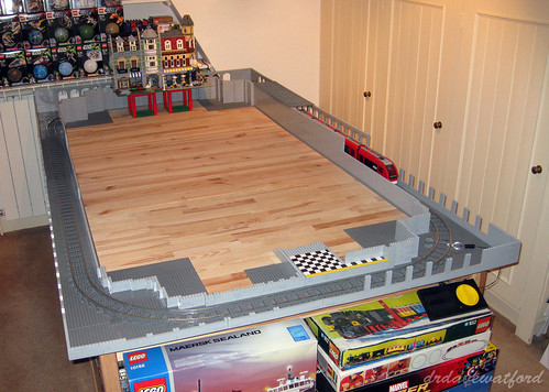
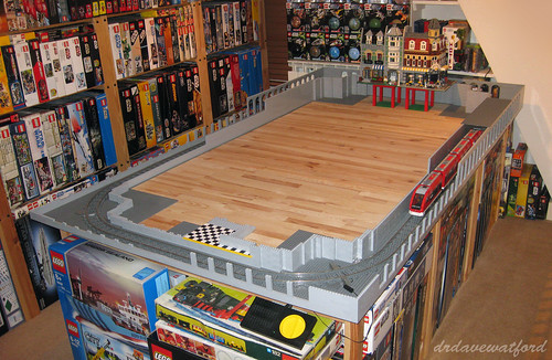
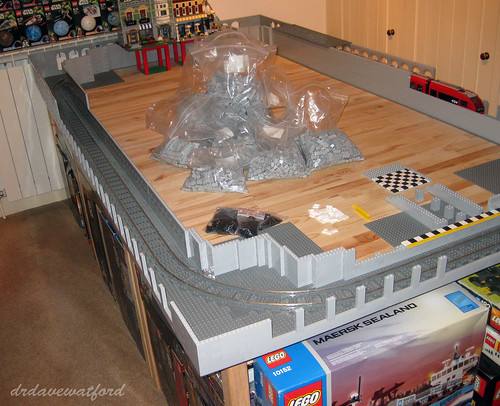
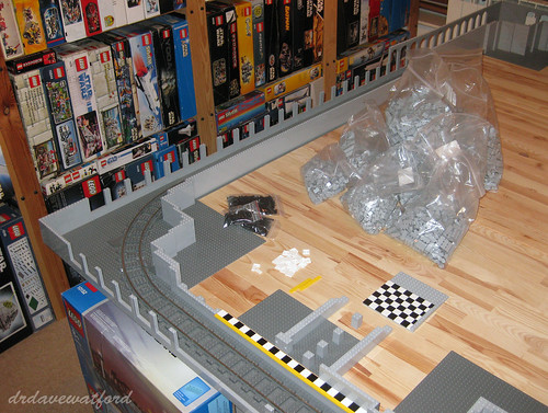
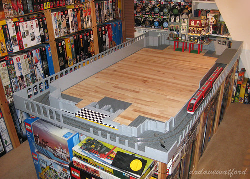
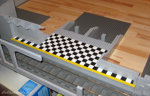
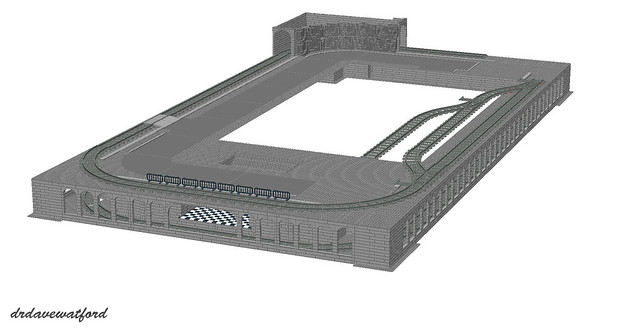
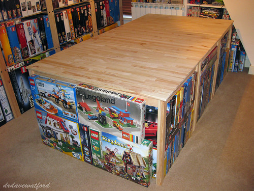
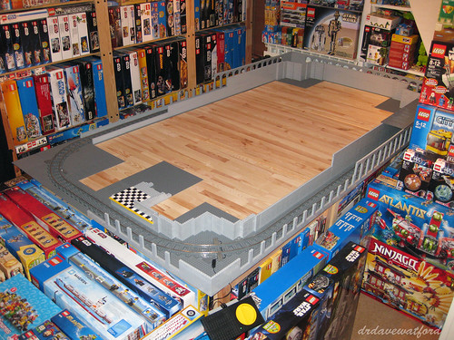
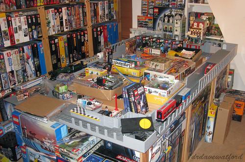
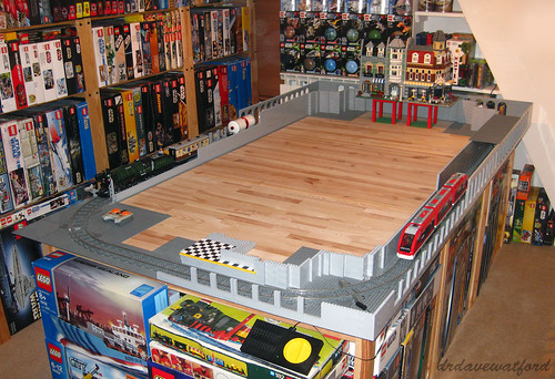
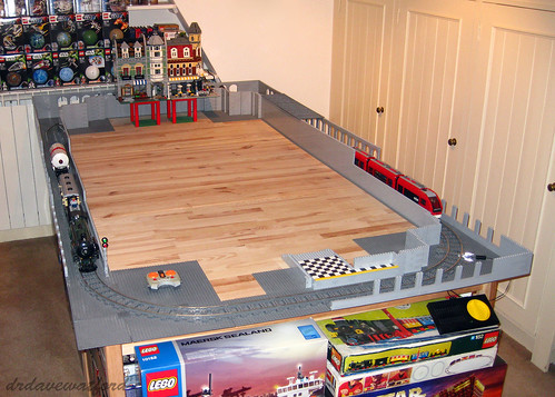
Step 2 : Attach the legs. Before I even attempted this came the realisation that with the legs attached, the AT-AT would be too big for my rudimentary photographic layout.... So where to build and photograph it ? Well, I didn't want to assemble it on my floor on the basis that the carpet wouldn't provide a firm base for the AT-AT to stand on. That, and I really didn't fancy its chances of surviving for long on the floor in the middle of my study. A solution was found in the form of the tables which support my work-in-progress LEGO City layout; thanks to my glacial rate of progress (yes, yes - I know I promised to provide an update on that project about a year ago, but I've been busy....) there's still a huge empty space in the middle of it. A space big enough for a colossal AT-AT, in fact. The downside is that there's no nice plain backdrop there to photograph the AT-AT against, so apologies for that - you'll just have to live with the distracting background until I can find a way of properly photographing it....

OK, adequate space located, it was time to figure out how on earth to go about precariously perching the body on top of the legs. Having tried to lift the body with one hand a few months back with catastrophic results (my hand-hold came away from the body, which proceeded to plummet to the floor and distintegrate on hitting the floor....) I decided to call for help. Pete tells me he's built a handle for the body of his AT-AT to allow him to attach the legs single-handedly, but I've yet to do this, and so it was that my reluctant wife was called into action and asked to hold the body of the AT-AT at just the right height for me to attach the legs. Attaching the legs involved threading a single Technic axle through the top of each leg and into the lower part of the body; the outer end of each axle also holds in place the large printed dishes that you can see at the top of each leg. Once each leg was attached, there came a point when I had to tell my wife to carefully let go of the body to see whether the legs would support the weight without collapsing. I don't mind admitting that this was incredibly nerve-wracking - if I hadn't seen Pete's AT-AT in the flesh I would have doubted that the legs could hold the weight. We both held our breath, but thankfully the legs held firm, and with a huge sigh of relief I stepped back and recorded the moment for posterity below (click to enlarge).


Step 3 : Attach the sides of the body. Here the concern was less about actually attaching the sides to the body and more about the fear that all the pushing and pulling involved in getting the sides into the right position and bolting them to the Technic frame would destabilise the legs, causing them to give way and bring everything crashing down. The other potential problem I faced was the fragility of the sides themselves - as previously described they're not very robust and have a tendency to break apart at the slightest excuse. In the event, attaching the sides turned out to be reasonably straightforward and didn't even require the help of my glamorous assistant. The sides are suspended from the top of the body's Technic frame by a couple of Technic pins with stop bush, and they rest at the correct angle relative to the body as a result of being pushed outwards by the platforms projecting from the sides of the body. The only complication did in fact turn out to be the fragility of the sides themselves - they broke apart a couple of times while I was trying to manipulate them into the correct position for attachment, setting me back a few minutes on each occasion while I effected a repair. Eventually it was done, and you can see the AT-AT with one and then both sides attached below (click pictures to enlarge).


Step 4 : Attach the head. This somewhat unexpectedly turned out to be one of the trickiest jobs. As you can see in the pictures above, projecting forwards from the front of the neck is a black rectangular structure with a couple of bley tiles on top and a bley Technic pin sticking out of the front. This structure slides into a slot inside the AT-AT's head, and the pin anchors it when it's in the correct position. Sounds simple. Lining up the head, getting the structure into the slot and getting the pin to click into place took a number of attempts, though, and all the while I was sweating that all the pushing and pulling would make the whole thing collapse. The head is quite fragile, and with all the pressure I was applying I managed to break the windscreen and roof section off the head. This however turned out to be a blessing in disguise as it ended up being easier to slide the head on to the neck without the roof being attached as I could better see what I was doing. Once the head was locked into position I carefully replaced the roof and windscreen and took the picture below (click to enlarge); the gap between the side of the head and the roof is a little wider than it should be as a result of all the pushing and pulling but this should be easy enough to fix with a bit of careful manipulation...


Step 5 : Cover the body. The roof which covers the body of the AT-AT consists of 3 distinct sections which are dropped into place one at a time. Fitting the roof sections was pretty straightforward - all sit on top of the upper edges of the sides of the body - and the fit was mostly pretty good although a little final tweaking is still needed in a couple of places. Also, the rear section has a tendency to slide backwards, and I'm going to need to add a stop to the underside to prevent this. The completed AT-AT with the roof sections fitted can be seen below.


And the finishing touch ? Well, no Star Wars UCS model is complete without a display plaque to go with it, and fellow AT-AT builder Morten has designed a suitable display sticker (below) which I now have a copy of, so thanks, Morten !


And so more than 11 months after I published my first post about building a copy of Pete's AT-AT it's finally finished ! Although I've seen Pete's original on a number of occasions I have to admit that I was still taken aback by the sheer size of the thing when I'd finished building my own - it's absolutely huge ! The scale is somewhat hard to convey, but the rebel pilot minifigure that I've posed on the top of the AT-AT's body in the picture below (click to enlarge) should hopefully give you a sense of how massive it is....


Regarding the final piece count, it was around 6,220, give or take; I can't offer an exact figure as it's calculated from the first draft of the LDD files which contain a few errors as previously mentioned, plus I've made a few minor modifications along the way to improve stability. So let's say 6,250 for the sake of argument. And the cost ? Well, I had around a third of the pieces already, and I estimate that the rest cost me about £600 including shipping, although I'm certain I could have done it cheaper if I'd shopped around more; I believe that fellow AFOL Rocao recently managed to source the necessary parts for around $600 excluding shipping, and Pete reckons that the whole lot only cost him £250...(!)

And lastly, was it worth the effort and the cost ? Well, on the one hand I can safely say that it's been quite the most frustrating build I've ever experienced, by a country mile. Admittedly this was in part because I was to some extent a guinea pig. working with the first draft of Pete's LDD files, but mostly it's just because it's a mighty tricky build at times. It's also nerve-wracking to put all the sections together, wildy impractical to display, and can't be moved when constructed.... But despite all of that, just look at the thing ! As a huge Star Wars fan, and indeed someone for whom the AT-AT is perhaps my favourite vehicle from the Star Wars universe, it's definitely been worth all the expense and pain to see this monster standing proudly in my house. Massive kudos to Pete for designing the thing and putting together a set of LDD files for it, and if anyone wants to get hold of a copy of the most recent version of the LDD files and have a go at building one yourself then please get in touch and I'll forward your details to Pete.

So what now ? Well, plans are afoot to show the AT-AT later this year at a public event where it'll be part of a display featuring a number of big Star Wars MOCs - I'll share more details in due course. Until then I think I'll just stare at the finished model with a huge grin on my face while I decide what to build next....

 < -- Building the AT-AT : Part 10

Wednesday, 26 June 2013

UCS AT-AT : The Home Straight

So, not far short of one whole year after I published the first blog posting on my quest to build a copy of Cavegod's UCS AT-AT (you can read about how it all began here if you missed it) I finally find myself in clear sight of the finishing line, and with only one section left to build before I can finally put all the sections together.

A year, it seems, is a long time in the world of Star Wars MOCs; Cavegod (Pete) has teased me mercilessly about my slow rate of progress, and fellow AT-AT builder Morten has also recently started to wind me up about the time it's taking, while texting me pictures of his amazing UCS Nebulon B Frigate which he's also managed to finish in the time it's taken me to not-yet-finish the AT-AT....

The final remaining section is the right side of the body; I think I dragged my heels even more than usual recently because I struggled so much building the left side. Thing is, I do actually have a deadline for finishing the AT-AT - October of this year, of which more in a future posting - so I figured that I really needed to pull my finger out and get on with it. With this in mind, I booted up LDD and loaded up the last remaining LDD file (picture below - click to enlarge).


As discussed at length in my previous AT-AT posting, brick outlines are at last once again visible for me on LDD after an extended period of them being greyed out in the menu and inaccessible; it makes following the building guide one hell of a lot easier. As you can see in the bottom left-hand corner of the picture, the right side of the body consists of a total of 722 pieces, which is a dead giveaway that it isn't just a mirror image of the 720 piece left side.

As you might expect with something of this size, generating the building guide (which thankfully only requires a single click of the green and yellow button visible on the top right of the screengrab above) takes a couple of minutes. Interestingly, the building guide for the left side of the AT-AT body split the build into front, mid, rear and lower sections. The guide for the right side just dives straight in to the mid-section, however, and then literally continues the build into the rear and lower sections as you can see in the example page from the building guide below; only the front section is built separately and attached in the final step. There's really no good reason for this difference in approach, but then I've long since given up trying to understand the eccentricities of the LDD building guide generator - it's a law unto itself, and I suspect that any attempt to second guess anything it does would be futile.


As some of you will recall, I had massive problems with the left side of the AT-AT body, specifically attaching the front and rear sections to the larger mid-section. This was mainly because the sub-assemblies which join the sections together - basically a whole bunch of 2 x 3 slopes mounted on a couple of long plates - were warped and therefore struggled to bear any weight. Anyway, I think I figured out the cause of the warping.... Below (click to enlarge) you can see a picture of two 2 x 3 slopes placed upside down and side by side. The slope on the left is from the batch that I used to build the left side of the body; if you look closely at the two anti-studs on the underside you can see that their walls are thickened in some areas. The slope on the right is from a new batch that I bought when I got suspicious that there was a problem with the slopes I'd used for the left side; here the anti-studs don't have corresponding areas of thickening on their walls. I used the new batch of slopes to build the right side of the body and the warping issue was far less evident. I'm not sure if the slope on the left is from a faulty batch, or if it's a normal variant - if any readers can shed any light on this then please post a comment or drop me an e-mail. I'm pretty sure however that this 'feature' was at the root of my problems, and I'll swap out the faulty (?) slopes from the left side too when I get a chance.


Having identified the above problem in advance of getting started on the right side of the body, construction turned out to be reasonably straightforward, and was accomplished in just a few hours spread over 3 evenings. The front section was a bit unstable and needed some simple modification to stiffen it up a bit, but otherwise everything came together with relatively little fuss, and you can see the end result below (click to enlarge).


Taking a close look at the picture above, I can see that some of the joins between the various sections aren't as tight as they might be, but that should be fairly easily remedied with a bit of (carefully applied) pressure in appropriate areas; the fact that I was reluctant to apply much in the way of brute force to push all the sections together is a reflection of my bad previous experiences with the left side of the body when the application of just a little too much pressure in the wrong place was enough to break the blasted thing into many pieces....

As previously stated, the two sides of the AT-AT aren't symmetrical. Both the front and rear sections below (click to enlarge) are slightly diffferent from their counterparts on the left side of the body. Anyone out there with time on their hands can therefore feel free to play a game of "AT-AT spot the difference" should they so desire, although if that's you then you might want to consider getting out more.


One thing of note on the rear section above is the flash of blue visible in the upper left quadrant. This is down to a couple of blue Technic half pins. I really need to ask Pete whether this is intentional, or whether something's supposed to be attached to them; in the event that they're actually supposed to look that way I'll replace them with the equivalent parts in bley.

So that's it, then - all sections completed, and 6215 pieces used by my best estimate (plus a few extras to provide a little additional stability in places). Which means that all that should be left for me to do is the small matter of joining all the completed sections together into the finished AT-AT - not long to wait now !

 < -- Building the AT-AT : Part 9                              Building the AT-AT : Part 11 -- >