Showing posts with label UCS. Show all posts

Wednesday, 17 September 2014

Race Against Time

I'm a notoriously slow builder. Set 10179 Ultimate Collector's Millennium Falcon took me the best part of 3-months to complete, and it's a source of some amusement to certain AFOL friends of mine that it takes me so long to finish my builds. It's not so much that the process of finding each piece and placing it in the correct position takes forever, more that I take frequent breaks while I build, some of which have a tendency to last days, or occasionally weeks, rather than minutes.... I certainly like to savour my building time, that's for sure, rather than rushing things too much. After all - what's the hurry?


Given all this, you might consider that a recent request from Fairy Bricks head honcho Kevin Gasgoigne for me to live-build a large model over the course of a weekend on behalf of the Fairy Bricks charity might be somewhat foolhardy.... For those who aren't aware, Fairy Bricks raises money to buy LEGO sets which it donates to childrens' wards at hospitals and hospices, and Gimme LEGO is proud to consider itself a Friend of Fairy Bricks. The charity was due to have a presence at the recent Bright Bricks and Bricks UK Exhibition of LEGO at Sandown Park racecourse, and the plan was for me to live-build Set 10234 Sydney Opera House during the show as a way of encouraging people to buy tickets for the raffle where the first prize was a new and sealed copy of the set. I have to admit that I had my doubts - at 2989 pieces the set is by my reckoning the 11th largest that LEGO have ever produced, and I was only going to be able to attend the show for a day and a half as I had a couple of other commitments to fit in. All that having been said, it was obviously a request that I couldn't refuse. I therefore agreed, albeit with some degree of trepidation, and so it was that a couple of months later I found myself heading down to Sandown Park racecourse in Epsom, South London on a crisp Saturday morning.


So how does a laid-back builder go about constructing a 2989-piece collossus in a day and a half? Well, apart from a generous supply of caffeine and chocolate, I figured that I'd just have to get my head down and focus - no mean feat given that I'd be building the model in a crowded and noisy exhibition hall. Shortly after arrival at the venue I was given custody of the set (above) and I wasted no time in slicing through the three tape seals at one end of the huge, bulging box and emptying out the contents - four instruction booklets sealed in a cardboard-backed bag, a bunch of blue baseplates, and a prodigious number of bags containing LEGO elements. Most of the bags are printed with a number corresponding to the instruction booklet that they're associated with, and in this way the build is split into four distinct stages. I'd brought along a few of the clear plastic crates that I use to sort pieces at home when I'm building large sets, so for each stage in turn I emptied out all the correspondingly numbered bags into a crate and roughly sorted them into small elements at one end and larger elements at the other to make finding pieces a bit easier. Parts-wise I've never seen so much dark tan in one place, so if you're looking for a dark tan parts pack then look no further....


The first instruction booklet, which consists of just 48 pages from cover to cover, guides you through construction of the area to the front of the Opera House (pictures above and below - click to enlarge). This part of the build is relatively quick and straightforward. Consisting mainly of a representation of the 100-metre wide ceremonial staircase known as the Monumental Steps which leads up to the two main performance venues, this first stage of the build sits on a couple of blue baseplates with a combined area of 32 x 48 studs. The separate structure which sits to the front of the Opera House is actually a restaurant, and its roof isn't completed until the very end of the build. The restaurant windows are comprised of black 6 x 6 and 10 x 10 round corner bricks which are cleverly positioned and held in place 'back to back', i.e. underside to underside, as you can (just about) see in the photographs.
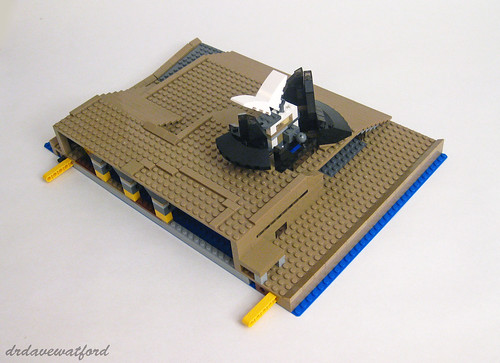

The second instruction booklet, which runs for a total of 72 pages, covers the construction of the rest of the Opera House and its surrounds, with the exception of the two main auditoria with their vaulted, sail-like roof structures and towering windows at the front and back. This section is mounted on a blue 48 x 48 baseplate which is unique to the set. By lunchtime on Saturday when I needed to sneak off elsewhere I'd been building for a total of approximately three and a half hours during which time I'd polished off the first instruction booklet and about a third of the second booklet.
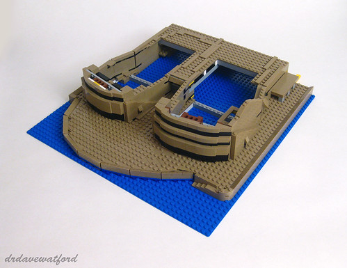

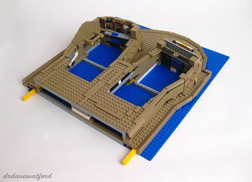
I arrived at the venue early on Sunday morning to crack on with the build, conscious that the pressure was well and truly on if I was going to finish up by 6 pm that day. I polished off the remainder of the second instruction booklet within a couple of hours, at which point Stage 2 of the build (pictures above and below - click to enlarge) was complete. The next job was to join the two completed sections together; this is achieved using just a couple of humble Technic pins, with the yellow Technic liftarms protruding from the base of each section acting as guides to ensure that the sections are correctly aligned relative to each other. While the second section took a fair bit longer to complete than the first, the build was nevertheless once again quite straightforward. I thought the curved terrace section that you can see in the picture above was particularly nicely realised - the curve is approximated via the use of a number of 1 x 4 hinge plates and the area inside the curve is neatly filled in with a variety of wedge plates; if you look closely you can see a couple of awkwardly-shaped areas filled with two 2 x 4 wedge plates.

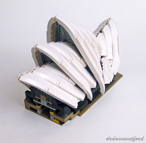
With the first two booklets completed it was time to move on to booklet three which contains instructions for construction of the larger of the Opera House's two main auditoria, the Concert Hall. In the model, the space beneath the sail-like roof is almost entirely filled with the structures which support the different roof elements and hold them at the correct angles. In comparison to the previously completed sections of the build, construction of the roof was trickier and needed a little care and concentration. The roof sections are held in place by a number of Technic A-frames which are angled via the use of ball-and-socket joints; it's pretty ingenious and the result is instantly recognisable, although if I have a criticism it's that the gap running along the apex of the roof isn't aesthetically very pleasing. In truth, however, it's hard to see how this could have been avoided.
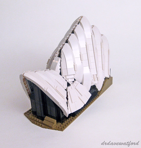

You can see pictures of the completed Concert Hall above (front view) and below (rear view), with the sail-like roof sections bookended by large expanses of glass. The picture below nicely demonstrates how the different roof sections are held at different angles via the use of ball and socket joints as previously described.

Once instruction booklet three was done and dusted I felt like I was on the home straight. Without further ado I dived into instruction booklet four and the final part of the build.  This commenced with construction of the smaller of the two main auditoria - the Joan Sutherland Theatre. I was on a roll by this time, and with the end in sight I steamed through this section in double-quick time.
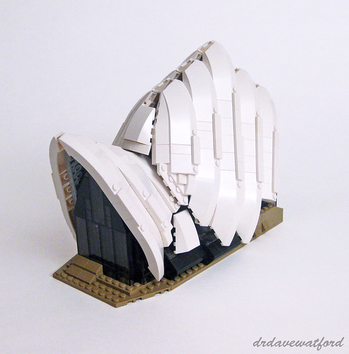

While not identical to the Concert Hall, construction of the Joan Sutherland Theatre predictably followed along very similar lines which inevitably provoked a sense of deja vu. That having been said, a degree of repetition is almost inevitable in a build of this size. You can see pictures of the completed Joan Sutherland Theatre above (front view) and below (rear view).
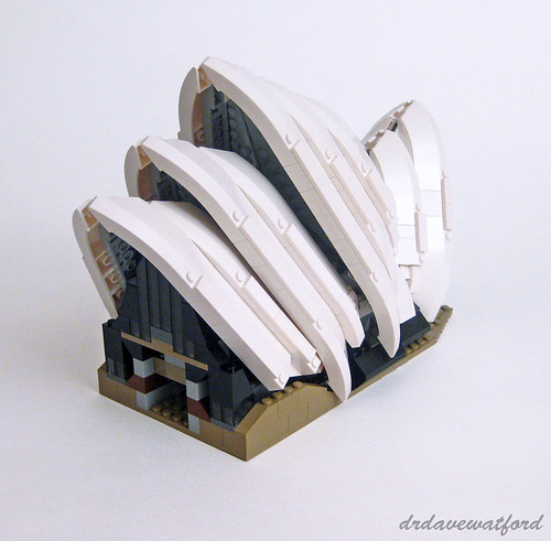

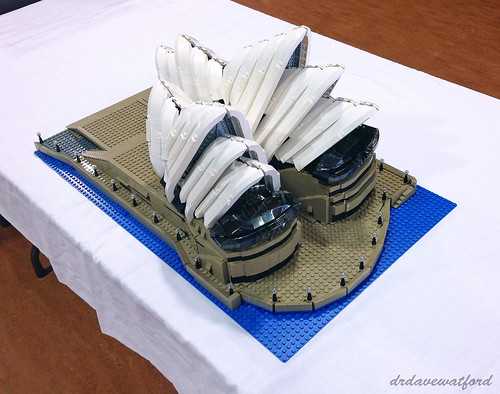
The completed Concert Hall and Joan Sutherland Theatre sections could then be dropped into their respective slots in the structure below, at which point Sydney Opera House was almost finished. Both auditoria are only attached underneath by a few studs but that's nevertheless more than enough to hold them securely in place. All that was left to do was to construct the curved glass structures at the rear of each auditorium, build and attach the restaurant roof, place 28 lamp posts onto the boardwalk around the sides of the building, and I was done ! You can see various views of the completed model below (click to enlarge).


Total build time turned out to be a little over 9 hours which was less than I'd expected. I'm pretty sure that I could have shaved some time off that if I'd been more focused and less easily distracted by visitors on the day, but chatting to attendees was a lot more interesting and worthwhile than trying to finish up more quickly, and it made for a far more memorable experience as far as I was concerned.
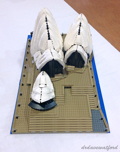

Prior to getting started, I did have some concerns that the build might be a bit dull thanks to the degree of repetition and necessarily bland colour palette employed. In the event, however, while there certainly was some repetition, it actually turned out to be a surprisingly interesting build, not least because of the number and variety of clever building techniques employed; construction of the 'sails' was particularly ingenious. With regard to the finished model, while I'm aware that some people who know Sydney Opera House much better than I do have expressed reservations about the accuracy and proportions of the model, to my untrained eye it seems to be a pretty good approximation.

Much more important than whether or not I enjoyed the build was of course whether it had the desired effect on raffle ticket sales. Kevin stood close by and sold tickets while I cracked on with the build, and our double act did seem to bear fruit - visitors would watch me build for a while, whereupon Kevin would appear and casually inform them that they could win their very own new and sealed copy of the set for just the cost of a £1 raffle ticket. All told, around £2,000 was raised from raffle ticket sales by the time the raffle draw took place late on Monday afternoon, so a big hand to Kevin and many thanks to all those attendees who bought a ticket.
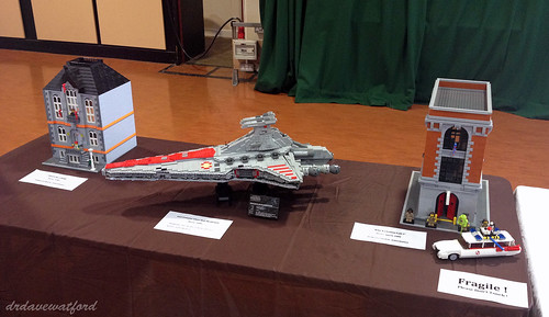

The Sandown Park show itself, which was being held for the first time, was a great success, attracting almost 4,700 visitors over the 3 days which was apparently way beyond the expectations of the organisers. I'd brought a few MOCs (above - click to enlarge) to exhibit, all of which have previously featured on Gimme LEGO at one time or another. Thankfully Kevin had arranged for them to be on display adjacent to where I was building Sydney Opera House so I was able to chat to attendees about the models and answer any questions that came up. Which reminds me - thanks to the Gimme LEGO readers and Bricksetters who came over to say "hi" - it was good to meet you!


I had limited time to check out the models that other exhibitors had brought along, but I saw enough to be impressed by the high quality of exhibits. In addition to a healthy line up of new builds and previously-displayed models from a host of noted builders, professional LEGO builders Bright Bricks were in attendance and brought a number of excellent models along with them, including the amazing tropical seabed scene above (click to enlarge).

Given the success of the event, and the ability of the venue to accommodate larger numbers of exhibits and visitors if needed, I reckon there's a good chance that we'll be back there next year. I just hope my sore fingers have recovered by then....

Monday, 8 July 2013

UCS AT-AT : They think it's all over...

When I last wrote, the various AT-AT sections had finally been completed, so it should simply have been a case of putting them all together and the AT-AT would be done. As I'm sure you've gathered by now, however, nothing about this project has been simple, and there were actually a couple of things I'd need to do before I could embark upon final assembly....

Firstly, as I've mentioned a number of times during this seemingly interminable journey, the LDD files I've been following were in very much 'first draft' status when I received them, and predictably enough a number of issues have been identified. Cavegod (Pete), the AT-AT's designer, has dutifully revised the LDD files along the way, but there was consequently always going to be a need for me to make a few tweaks to the various completed sections prior to final assembly of the model. Much of the last week or so has therefore been spent making these modifications, some of which necessitated a wait for a couple of Bricklink orders to arrive.


The biggest issue to remedy involved the internal skeleton of the body (above) which thanks to a mistake in the LDD file ended up one stud too long and therefore needed chopping down to size. This sounds potentially quite involved, but in practice it wasn't too big a deal, particularly as Pete has now revised the offending LDD file so I could closely study the necessary modifications and implement them. A further issue concerned the dark bley platforms which project out from the sides of the body, one on each side (you can see one of them in the picture above); these structures were unfinished and slightly out of position on the original LDD file. Once again the LDD file has now been corrected, and thankfully the necessary modifications were straightforward, although they did require a few additional parts.


Lastly, I decided to make a couple of tweaks to increase the stability of the legs as I was nervous about their ability to support the weight of the AT-AT's body. The joint between the foot and the lower part of the leg (above) isn't very strong, and as a consequence, when the leg pivots at the ankle and the weight of the body is applied there's a risk of the leg giving way. This is guaranteed to bring 6000+ pieces crashing down so is to be avoided if at all possible.... Following some discussion, Pete suggested a simple modification to help support the leg when it's in a flexed position, and in addition to this I made a couple of further tweaks to increase the strength of the ankle joint and offer additional support and stability. Only when these had been completed did I feel sufficiently confident to proceed with final assembly of the AT-AT.

So here we go, then.... Step 1 : Attach neck to body. A couple of Technic pins protruding forward from the front of the body act as a guide to ensure that the neck is in position, after which the neck can be firmly bolted on by threading a bley Technic axle down through a series of interlocking, overlapping Technic liftarms sticking out from the neck and body. You can see the results below - click the pictures to enlarge them.


Step 2 : Attach the legs. Before I even attempted this came the realisation that with the legs attached, the AT-AT would be too big for my rudimentary photographic layout.... So where to build and photograph it ? Well, I didn't want to assemble it on my floor on the basis that the carpet wouldn't provide a firm base for the AT-AT to stand on. That, and I really didn't fancy its chances of surviving for long on the floor in the middle of my study. A solution was found in the form of the tables which support my work-in-progress LEGO City layout; thanks to my glacial rate of progress (yes, yes - I know I promised to provide an update on that project about a year ago, but I've been busy....) there's still a huge empty space in the middle of it. A space big enough for a colossal AT-AT, in fact. The downside is that there's no nice plain backdrop there to photograph the AT-AT against, so apologies for that - you'll just have to live with the distracting background until I can find a way of properly photographing it....

OK, adequate space located, it was time to figure out how on earth to go about precariously perching the body on top of the legs. Having tried to lift the body with one hand a few months back with catastrophic results (my hand-hold came away from the body, which proceeded to plummet to the floor and distintegrate on hitting the floor....) I decided to call for help. Pete tells me he's built a handle for the body of his AT-AT to allow him to attach the legs single-handedly, but I've yet to do this, and so it was that my reluctant wife was called into action and asked to hold the body of the AT-AT at just the right height for me to attach the legs. Attaching the legs involved threading a single Technic axle through the top of each leg and into the lower part of the body; the outer end of each axle also holds in place the large printed dishes that you can see at the top of each leg. Once each leg was attached, there came a point when I had to tell my wife to carefully let go of the body to see whether the legs would support the weight without collapsing. I don't mind admitting that this was incredibly nerve-wracking - if I hadn't seen Pete's AT-AT in the flesh I would have doubted that the legs could hold the weight. We both held our breath, but thankfully the legs held firm, and with a huge sigh of relief I stepped back and recorded the moment for posterity below (click to enlarge).


Step 3 : Attach the sides of the body. Here the concern was less about actually attaching the sides to the body and more about the fear that all the pushing and pulling involved in getting the sides into the right position and bolting them to the Technic frame would destabilise the legs, causing them to give way and bring everything crashing down. The other potential problem I faced was the fragility of the sides themselves - as previously described they're not very robust and have a tendency to break apart at the slightest excuse. In the event, attaching the sides turned out to be reasonably straightforward and didn't even require the help of my glamorous assistant. The sides are suspended from the top of the body's Technic frame by a couple of Technic pins with stop bush, and they rest at the correct angle relative to the body as a result of being pushed outwards by the platforms projecting from the sides of the body. The only complication did in fact turn out to be the fragility of the sides themselves - they broke apart a couple of times while I was trying to manipulate them into the correct position for attachment, setting me back a few minutes on each occasion while I effected a repair. Eventually it was done, and you can see the AT-AT with one and then both sides attached below (click pictures to enlarge).


Step 4 : Attach the head. This somewhat unexpectedly turned out to be one of the trickiest jobs. As you can see in the pictures above, projecting forwards from the front of the neck is a black rectangular structure with a couple of bley tiles on top and a bley Technic pin sticking out of the front. This structure slides into a slot inside the AT-AT's head, and the pin anchors it when it's in the correct position. Sounds simple. Lining up the head, getting the structure into the slot and getting the pin to click into place took a number of attempts, though, and all the while I was sweating that all the pushing and pulling would make the whole thing collapse. The head is quite fragile, and with all the pressure I was applying I managed to break the windscreen and roof section off the head. This however turned out to be a blessing in disguise as it ended up being easier to slide the head on to the neck without the roof being attached as I could better see what I was doing. Once the head was locked into position I carefully replaced the roof and windscreen and took the picture below (click to enlarge); the gap between the side of the head and the roof is a little wider than it should be as a result of all the pushing and pulling but this should be easy enough to fix with a bit of careful manipulation...


Step 5 : Cover the body. The roof which covers the body of the AT-AT consists of 3 distinct sections which are dropped into place one at a time. Fitting the roof sections was pretty straightforward - all sit on top of the upper edges of the sides of the body - and the fit was mostly pretty good although a little final tweaking is still needed in a couple of places. Also, the rear section has a tendency to slide backwards, and I'm going to need to add a stop to the underside to prevent this. The completed AT-AT with the roof sections fitted can be seen below.


And the finishing touch ? Well, no Star Wars UCS model is complete without a display plaque to go with it, and fellow AT-AT builder Morten has designed a suitable display sticker (below) which I now have a copy of, so thanks, Morten !


And so more than 11 months after I published my first post about building a copy of Pete's AT-AT it's finally finished ! Although I've seen Pete's original on a number of occasions I have to admit that I was still taken aback by the sheer size of the thing when I'd finished building my own - it's absolutely huge ! The scale is somewhat hard to convey, but the rebel pilot minifigure that I've posed on the top of the AT-AT's body in the picture below (click to enlarge) should hopefully give you a sense of how massive it is....


Regarding the final piece count, it was around 6,220, give or take; I can't offer an exact figure as it's calculated from the first draft of the LDD files which contain a few errors as previously mentioned, plus I've made a few minor modifications along the way to improve stability. So let's say 6,250 for the sake of argument. And the cost ? Well, I had around a third of the pieces already, and I estimate that the rest cost me about £600 including shipping, although I'm certain I could have done it cheaper if I'd shopped around more; I believe that fellow AFOL Rocao recently managed to source the necessary parts for around $600 excluding shipping, and Pete reckons that the whole lot only cost him £250...(!)

And lastly, was it worth the effort and the cost ? Well, on the one hand I can safely say that it's been quite the most frustrating build I've ever experienced, by a country mile. Admittedly this was in part because I was to some extent a guinea pig. working with the first draft of Pete's LDD files, but mostly it's just because it's a mighty tricky build at times. It's also nerve-wracking to put all the sections together, wildy impractical to display, and can't be moved when constructed.... But despite all of that, just look at the thing ! As a huge Star Wars fan, and indeed someone for whom the AT-AT is perhaps my favourite vehicle from the Star Wars universe, it's definitely been worth all the expense and pain to see this monster standing proudly in my house. Massive kudos to Pete for designing the thing and putting together a set of LDD files for it, and if anyone wants to get hold of a copy of the most recent version of the LDD files and have a go at building one yourself then please get in touch and I'll forward your details to Pete.

So what now ? Well, plans are afoot to show the AT-AT later this year at a public event where it'll be part of a display featuring a number of big Star Wars MOCs - I'll share more details in due course. Until then I think I'll just stare at the finished model with a huge grin on my face while I decide what to build next....

 < -- Building the AT-AT : Part 10

Wednesday, 26 June 2013

UCS AT-AT : The Home Straight

So, not far short of one whole year after I published the first blog posting on my quest to build a copy of Cavegod's UCS AT-AT (you can read about how it all began here if you missed it) I finally find myself in clear sight of the finishing line, and with only one section left to build before I can finally put all the sections together.

A year, it seems, is a long time in the world of Star Wars MOCs; Cavegod (Pete) has teased me mercilessly about my slow rate of progress, and fellow AT-AT builder Morten has also recently started to wind me up about the time it's taking, while texting me pictures of his amazing UCS Nebulon B Frigate which he's also managed to finish in the time it's taken me to not-yet-finish the AT-AT....

The final remaining section is the right side of the body; I think I dragged my heels even more than usual recently because I struggled so much building the left side. Thing is, I do actually have a deadline for finishing the AT-AT - October of this year, of which more in a future posting - so I figured that I really needed to pull my finger out and get on with it. With this in mind, I booted up LDD and loaded up the last remaining LDD file (picture below - click to enlarge).


As discussed at length in my previous AT-AT posting, brick outlines are at last once again visible for me on LDD after an extended period of them being greyed out in the menu and inaccessible; it makes following the building guide one hell of a lot easier. As you can see in the bottom left-hand corner of the picture, the right side of the body consists of a total of 722 pieces, which is a dead giveaway that it isn't just a mirror image of the 720 piece left side.

As you might expect with something of this size, generating the building guide (which thankfully only requires a single click of the green and yellow button visible on the top right of the screengrab above) takes a couple of minutes. Interestingly, the building guide for the left side of the AT-AT body split the build into front, mid, rear and lower sections. The guide for the right side just dives straight in to the mid-section, however, and then literally continues the build into the rear and lower sections as you can see in the example page from the building guide below; only the front section is built separately and attached in the final step. There's really no good reason for this difference in approach, but then I've long since given up trying to understand the eccentricities of the LDD building guide generator - it's a law unto itself, and I suspect that any attempt to second guess anything it does would be futile.


As some of you will recall, I had massive problems with the left side of the AT-AT body, specifically attaching the front and rear sections to the larger mid-section. This was mainly because the sub-assemblies which join the sections together - basically a whole bunch of 2 x 3 slopes mounted on a couple of long plates - were warped and therefore struggled to bear any weight. Anyway, I think I figured out the cause of the warping.... Below (click to enlarge) you can see a picture of two 2 x 3 slopes placed upside down and side by side. The slope on the left is from the batch that I used to build the left side of the body; if you look closely at the two anti-studs on the underside you can see that their walls are thickened in some areas. The slope on the right is from a new batch that I bought when I got suspicious that there was a problem with the slopes I'd used for the left side; here the anti-studs don't have corresponding areas of thickening on their walls. I used the new batch of slopes to build the right side of the body and the warping issue was far less evident. I'm not sure if the slope on the left is from a faulty batch, or if it's a normal variant - if any readers can shed any light on this then please post a comment or drop me an e-mail. I'm pretty sure however that this 'feature' was at the root of my problems, and I'll swap out the faulty (?) slopes from the left side too when I get a chance.


Having identified the above problem in advance of getting started on the right side of the body, construction turned out to be reasonably straightforward, and was accomplished in just a few hours spread over 3 evenings. The front section was a bit unstable and needed some simple modification to stiffen it up a bit, but otherwise everything came together with relatively little fuss, and you can see the end result below (click to enlarge).


Taking a close look at the picture above, I can see that some of the joins between the various sections aren't as tight as they might be, but that should be fairly easily remedied with a bit of (carefully applied) pressure in appropriate areas; the fact that I was reluctant to apply much in the way of brute force to push all the sections together is a reflection of my bad previous experiences with the left side of the body when the application of just a little too much pressure in the wrong place was enough to break the blasted thing into many pieces....

As previously stated, the two sides of the AT-AT aren't symmetrical. Both the front and rear sections below (click to enlarge) are slightly diffferent from their counterparts on the left side of the body. Anyone out there with time on their hands can therefore feel free to play a game of "AT-AT spot the difference" should they so desire, although if that's you then you might want to consider getting out more.


One thing of note on the rear section above is the flash of blue visible in the upper left quadrant. This is down to a couple of blue Technic half pins. I really need to ask Pete whether this is intentional, or whether something's supposed to be attached to them; in the event that they're actually supposed to look that way I'll replace them with the equivalent parts in bley.

So that's it, then - all sections completed, and 6215 pieces used by my best estimate (plus a few extras to provide a little additional stability in places). Which means that all that should be left for me to do is the small matter of joining all the completed sections together into the finished AT-AT - not long to wait now !

 < -- Building the AT-AT : Part 9                              Building the AT-AT : Part 11 -- >

Thursday, 18 April 2013

UCS AT-AT : Raising the Roof

Having struggled through the construction of the AT-AT's left side last time out, I couldn't bear the thought of building the right side quite yet, so I decided to skip it for now and build the roof next instead. The roof will eventually be suspended above the internal skeleton and body of the AT-AT. On the basis of the LDD file, the roof, which is made up of just 346 pieces, looked like it'd be fairly simple to build, and would thus provide some welcome light relief.


You can see a screenshot of the LDD file for the roof above (click to enlarge). Shortly before loading up the LDD file I was delighted to finally figure out how to reactivate the "Outlines on bricks" option on LDD which had mysteriously disappeared after I upgraded to the latest version of the Mac OS a while back. If anyone else has been struggling with this issue, the fix involves going into the 'Preferences' menu in LDD and checking both the "High-quality rendering..." boxes, whereupon the greyed-out "Outlines on bricks" option will be magically available for you to select. Thanks are due to Eurobricks member vynsane for this invaluable tip.


LDD quickly generated the building guide (sample page above - click to enlarge) which consisted of 118 steps. Brick outlines were thankfully also visible on the building guide which made following along significantly easier. That having been said, the sample page above illustrates that LDD hasn't lost its ability to frustrate - a significant irritation during the construction of previous sections has been the software's propensity for generating building guides which bizarrely and totally unnecessarily leave multiple pieces floating in mid air until a later stage of the build, and that tendency is still very much in evidence here.

The roof of the AT-AT consists of 3 sections. The section at the front (picture below - click to enlarge) is the smallest and simplest part of the roof. It's just 2 plates thick, and aside from its mix of tiled and studded sections it has minimal detailing. Construction of this section takes just 15 steps of the building guide to accomplish, so it was done and dusted in a matter of minutes.


The mid-section of the roof (picture below) is the biggest component; while it's again just 2 plates thick over most of its area, it has various elements stuck on the surface or embedded within it; these are purely cosmetic, but add a welcome organic, random feel to a surface that might otherwise have been rather plain. I can't vouch for the accuracy of these details as movie stills which clearly show the top of an AT-AT from above are surprisingly hard to find, but knowing cavegod he'll have done his homework. Certainly the dark grey vent-like structures that you can see in the picture below extending downwards from the front of the mid-section are movie accurate, at least.


The rear-most section of the roof (below) was definitely the trickiest to build and has the most surface detailing. The hinged section at the very back, which consists of a number of 1 x 6 tiles that wrap around the back edge of the roof, is quite fragile and needs to be handled with care. The darker grey greebled section that you can see on the right side of the picture corresponds to the sample page of the building guide that I showed earlier, and it's those greebles that are supposed to be just left suspended in mid-air for a period if the building guide is to be followed religiously. LDD bashing aside, however, the greebling looks excellent and is certainly worth the effort.


You can see the three sections of the roof laid out in the pictures below (click to enlarge). The first picture shows the sections laid out from front to back as you move from the left side of the picture to the right, while the picture below it shows the sections from back to front. The roof sections aren't directly connected to each other; I'm guessing that each section will end up suspended between the upper edges of the left and right sides of the body, held in the correct position relative to the others by gravity alone. We shall see....


As expected, building the roof did indeed turn out to be pretty straightforward, nothwithstanding LDD's absurd sequencing of building steps. With another 346 pieces used up, by my reckoning I'm now almost 5,500 pieces into this massive build, and it's starting to sink in that with barely 700 pieces left to go I'm finally on the home straight. Next up I have the small matter of the right side of the AT-AT to assemble, and then it's crunch time (probably literally as well as metaphorically) as I take my life in my hands and try to put all the completed sections together......

 < -- Building the AT-AT : Part 8                               Building the AT-AT : Part 10 -- >

Monday, 18 February 2013

UCS AT-AT : Beside Myself...

Given my track record I'd be willing to bet that you weren't expecting another UCS AT-AT posting so soon; hell, it's barely 3 weeks since I posted the last update. Having moved things along nicely last time out by wrapping up the AT-AT's head, however, I had the bit between my teeth and decided to press on.

I've now built all four legs, the body, the head and the neck, so all that's left to construct is the outer shell which covers the body. This consists of left and right sides plus a roof to top it off. On the surface it sounds like I'm on the home straight, but when you consider that each side consists of over 700 pieces, I've still got the best part of 2,000 pieces to put together so I guess I shouldn't start counting my chickens quite yet.


You can see a screenshot of the LDD file for the left side of the body above; LDD has a useful feature which outlines all the bricks in a virtual build, but this capability unfortunately hasn't been available to me since I 'upgraded' to the latest version of Apple's Mac operating system - Mountain Lion (OS X 10.8.2). The left side of the AT-AT thus appears as a largely homogenous, ugly and uninformative grey wall across my screen when viewed in LDD. The lack of brick outlines also extends to the building guide generated by LDD which makes it harder to see how the different pieces fit together on the building guide - not good.

LDD's building guide generator took a good few minutes to generate the instructions, ultimately spitting out more than 200 building steps after cogitating for what seemed like ages. Same old same old, however - similar to previous sections, just a few steps into the build I found myself staring at multiple sub-assemblies and loose parts floating in mid air (below). This is fine if you're building in zero G, but not so convenient if like me you're subject to the usual laws of Earthly gravity.


Thankfully it's pretty obvious where all the floating bits and pieces eventually fit when the time comes to attach them, and after 64 steps I'd finished the rear-most section of the AT-AT's left side (picture below - click to enlarge) which has a typically nice greebled look to it. It was at times a challenge to prevent it from falling apart during the build, but it all came together OK in the end. This fragility would come back to haunt me later, however, as you'll discover in due course....


Steps 65 to 95 deal with the construction of the front-most section of the left side (below - click to enlarge). It's largely an exercise in stacking plates and topping them off with tiles, in marked contrast to the completed rear-most section which is predominantly brick-built. It's a fairly quick, straightforward build and thankfully pretty stable


Next up was the structure which under-hangs the large central section; this is rapidly dispatched in just 18 building steps, and then it's on to the central section itself. With a width of 24 studs and a height of more than 19 bricks, this is a somewhat time-consuming build but not particularly difficult. The LDD-generated building guide rather blots its copybook at times with a bizarre sequencing of building steps, such that if you were to follow them to the letter you'd frequently have to back-track and remove pieces you'd already placed in order to proceed with the build. Thankfully, however, it's pretty obvious how everything fits together and hard to go too far wrong.

Once the central section is completed, the lower, under-hanging portion attaches to the bottom via nine 1 x 2 hinges; these hold it firmly in place while allowing it to be positioned at the appropriate angle relative to the body, and you can see the results below (click pictures to enlarge).


Having completed the three different sections making up the left side of the body shell, and with only the job of joining them together remaining, I figured I was moments away from finishing this bit of the job. How wrong I was.... The first inkling I had that things wouldn't be quite so straightforward was while building the two structures below (click to enlarge). These are part of the central section, and it's to these 'linking structures' that the front and rear sections attach, thus knitting everything together. They're pretty simple, basically just consisting of a bunch of 3 x 2 slopes mounted on a couple of plates, and topped off with a load of hinge bases.


Anyway, for reasons I couldn't quite fathom, placing the slopes on the plates caused them to warp, so much so that the linking structures bore more than a passing resemblance to a couple of light bluish grey bananas. Even aside from any aesthetic concerns, this meant that I couldn't get them to attach securely on either side of the central section, which in turn meant that they were unable to support the weight of the front and rear sections. The problem was compounded by the connections between the central section and these linking structures being quite weak anyway, and this was particularly and infuriatingly evident when trying to attach the fragile rear section. Cue about an hour of cursing and frustration, characterised by the following cycle : (1) carefully and painstakingly attach the fragile rear section to the central section via the relevant linking structure, (2) fragile rear section immediately falls off and smashes, (3) rebuild fragile rear section, (4) apply pressure in order to try and re-attach rear section to central section more securely than before, (5) application of pressure causes fragile rear section to break apart in my hands, (6) rebuild fragile rear section again, (7) jump back to step (1) and repeat ad infinitum..... Gradually I was forced into making a few modifications which somewhat reduced the warping of the rear linking structure at least and also increased the clutch between the central section and the linking structures.

Eventually, and with a massive sigh of relief, I successfully attached the front and rear sections to the central section, and they stayed put. I was even able to move the whole completed build across the room and on to a black sheet so I could photograph it (picture below - click to enlarge). You don't have to look particularly hard to see that the join between the front section and central section in particular is not as tight as it should be, but I didn't dare apply any more pressure for fear of triggering the above cycle again, albeit at the front rather than the back....


So that's left side finished, and thank God for that. I'll obviously be able to apply what I've learned when I build the right side, so that should be polished off a lot quicker, and then the only section I'll have left to build is the roof. At this stage I don't even dare to think about what it'll be like trying to join all the sections together into the final completed AT-AT, but I know it's possible - I've seen the completed model "in the flesh" - and it's that which sustains me through all the trials and tribulations. Well, that, and also the knowledge that having spent hundreds and hundreds of pounds on this project, not to mention countless hours, if I fail you'll all give me tons of grief and wind me up mercilessly. That's also pretty motivating...

For the record, that's another 720 pieces down, meaning that I've now used up 5,149 of the pieces. Which means I have only a little over a thousand pieces left to go.

Before I go, just a reminder that if anyone wants a copy of the LDD files for this beast, please get in touch and I'll forward your details on to the AT-AT's designer Pete (cavegod).

< -- Building the AT-AT : Part 7                                    Building the AT-AT : Part 9 -- >